-
Notifications
You must be signed in to change notification settings - Fork 1
Notes about ros_control framework
Some general notes about the ros_control framework.
- it exposes standard ROS interfaces allowing other 3rd-party frameworks (MoveIt, NavStack, …) to drive the robot in a reasonably simple way
- no need of additional implementations for any controller of the robot
- a standard way to drive and control a robot in ROS framework
- support for the most common types of controllers
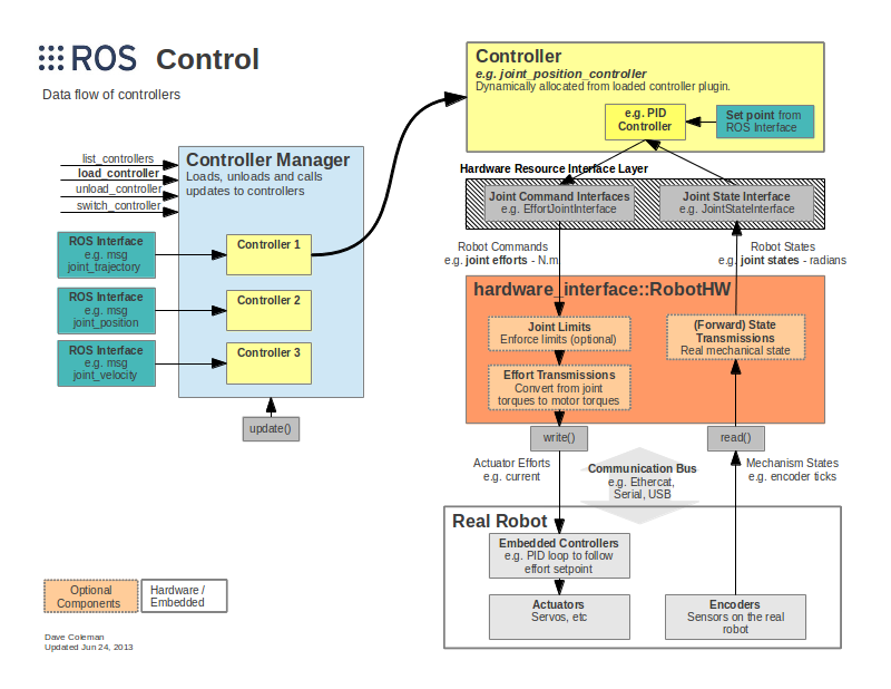
- Hardware Abstraction Layer — emulate/use real hardware, communicate with the robot using a communication BUS
- Controller manager — manage the set of the controllers; start, stop, and configure controllers
- transmission interface — specified in the URDF files
It is the core of ros_control, which serves as a bridge to different simulated and real robots, based on the roscpp class [hardware_interface::RobotHW](http://docs.ros.org/en/jade/api/hardware_interface/html/c++/classhardware__interface_1_1RobotHW.html), the father class for any robot-specific controller implementation.
In simple terms, this software is able both
- to communicate with hardware on a real robot
- and to simulate a real hardware implementation, with automatic integration with Gazebo and RViz
The framework is implemented in real time, because of the nature of the problem.
Here are some bullets describing the structure of the control layer controlling one joint. The same idea is applied to every type of joint you want.
Inputs:
- LOOP INPUT : the joint state, from encoders or something emulating them
- TARGET INPUT : the point to reach
Generation of the control signal:
- ros_control implements a loop control system for the joints, typically based on effort control
- usually it is a PID controller
In a nutshell, the framework controls each joint with a simple pipeline:
-
MOTOR — a joint is actuated by a motor, applying a force to make it move
in URDF we can define a “fake” motorusing the gazebo_ros_control plugin
-
HARDWARE INTERFACE — in order to control the motor, each motor has a hardware interface which takes a input and turns it into a effort command.
📎 see in particular → http://docs.ros.org/en/jade/api/hardware_interface/html/c++/joint__command__interface_8h_source.html
The simplest one is the effort joint interface which simply takes a force as input and converts it into a format understandable by the motor.
There are also a position interface and a velocity interface, with vlear meaning of terms.
-
LOW-LEVEL CONTROLLER — the controller is a block in a closed-loop system (see control theory, since we’re talking especially about low-level control). The overall loop generates a output compatible with the given hardware interface, taking as inputs the feedback of the system as well as the objective to reach.
Usually a PID controller is employed; their parameters are specified in the
motors_config.yamlfile. -
ROS CONTROL NODE INTERFACE — the ROS framework also provides some nodes making simpler to communicate with the low level infrastructure.
let’s assume to control the joint ???.
In the URDF/.gazebo file:
- transmission name:
???_trans - motor name:
???_motor
in config file:
- file name:
???(your namespace)_configor alsomotors_configis good - controller name:
???_controller
For ROS1 Noetic, use this:
sudo apt-get install -y ros-noetic-ros-control ros-noetic-ros-controllers ros-noetic-gazebo-ros-pkgs ros-noetic-gazebo-ros-control
👆 we’re strictly referring to a emulated environment here using both Gazebo and RViz.
📎 very interesting is this page → https://classic.gazebosim.org/tutorials?tut=ros_control
👆 Just a bit of notation for templating. Remember to replace ??? in the code with your custom names. In particular, ???(field) requires to replace the symbol ??? with something already defined in the previous steps. See the example:
<!-- insert here the name -->
<field>???</field>

<!-- remember to use here the same name! -->
???(field)it is needed in order to emulate the control through Gazebo simulation environment. Add this to your .gazebo file:
<gazebo>
	<plugin name="gazebo_ros_control" filename="libgazebo_ros_control.so">
		<robotNamespace>/???</robotNamespace>
	</plugin>
</gazebo>robotNamespace corresponds to the prefix of the config file, as well as the first tag of the yaml file specifying the PID controllers.
once defined the joint to control, you have to define its motor as a simple XML tag, as showed here below, already configured in the most typical way (remember to replace the ??? symbol with your names):
	<transmission name="???_trans">
	<type>transmission_interface/SimpleTransmission</type>
	<joint name="???">
		<hardwareInterface>hardware_interface/EffortJointInterface</hardwareInterface>
	</joint>
	<actuator name="???">
		<hardwareInterface>hardware_interface/EffortJointInterface</hardwareInterface>
		<mechanicalInterface>1</mechanicalInterface>
	</actuator>
</transmission>-
transmission_interface/SimpleTransmissionis the default transmission, always definedNotice that
transmission_interface/SimpleTransmissioncorresponds to the classtransmission_interface::SimpleTransmission. -
you can of course implement every other controller. See the links on the bottom of this page to find some already-available transmission types.
📎 In particular, see → http://wiki.ros.org/ros_control#Hardware_Interfaces
-
hardware_interface/EffortJointInterface— a control based on forces (the most typical control type) -
hardware_interface/VelocityJointInterface— velocity-based control -
hardware_interface/PositionJointInterface— it takes into account the target position only
Setting up the PID controllers is simple. Just add a .yaml file named ???_control.yaml in your config folder. Notice that ??? is your namespace specified in configuring the Gazebo plugin. The syntax is pretty much similar to the following one.
???(your_namespace):
	# --------------------------
	joint_state_controller:
		type: joint_state_controller/JointStateController
		publish_rate: 50

	# --------------------------
	# for each motor you defined ...
	???_controller:
		type: effort_controllers/JointPositionController
		joint: ???(name of the actuated joint)
pid: {p: ???, i:???, d:???}here’s a general template for launching the high-level abstraction of the controllers.
👆 Start this launch only after loaded the model in Gazebo.
<?xml version="1.0"?>
<launch>

<!-- list of all the motors inside the model -->
<arg name="motors" default="???(... all the names of the controllers)" />
<arg name="out" default="screen" />

<!-- load the parameters of the controllers in the param server -->
<rosparam file="$(find ???)/config/???.yaml" command="load"/>

<!-- load the controllers -->
<node name="controller_spawner" pkg="controller_manager" type="spawner"
	respawn="false" output="$(arg out)" ns="/???(your namespace)"
	args="$(arg motors)"/>

</launch>-
official page of ros_control → ROS wiki - ros_control
- in particular, see the Diagram of the system → ros_control main diagram
- here’s an additional resource about the framework as github wiki → ros_control gitHub wiki
- here’s the list of all the components under ros_control → list of nodes
- about the URDF interfaces → Transmission URDF interfaces
-
for further information about the ROS control framework, give a look at this paper → ros_control: a generic and simple control framewrk for ROS (full paper PDF)
- just for fun, see also this list of papers on the IIT site → robotic-software
- it is mentioned here as well → ros_controllers ROS wiki
-
GitHub repo for ROS controlers → ros-control/ros_controllers on GitHub
the repo is interesting even for the fact that it contains many examples helpfur for understanding how to implement your own controllers for your project.
In particular, give a look at
-
MoveIt official page, for path planning and manipulation → MoveIt
-
ROS NavStack, official documentation online, for autonomous navigation → ROS navigation Stack
-
about
hardware_interface::RobotHWroscpp class → http://docs.ros.org/en/jade/api/hardware_interface/html/c++/classhardware__interface_1_1RobotHW.html -
index of the messages for ros_control, the package containing them is → control_msgs
-
about the package → joint_trajectory_controller
-
ROS WIKI page about the transmission interface, a simple index of resources available online → transmission interface
-
an example about how to set a URDF model with Gazebo controllers → https://github.com/ros-simulation/gazebo_ros_demos/tree/kinetic-devel/rrbot_control
- you can find here some other demos → https://github.com/ros-simulation/gazebo_ros_demos
- official Gazebo page → https://gazebosim.org/home